Design a mod-5 synchronous counter using J-Kflip-flops, Computer

Counter Logic Circuit Diagram

Counter mod synchronous using diagram flops table flip logic computer karnaugh maps Binary counter circuit diagram using ic 555 timer

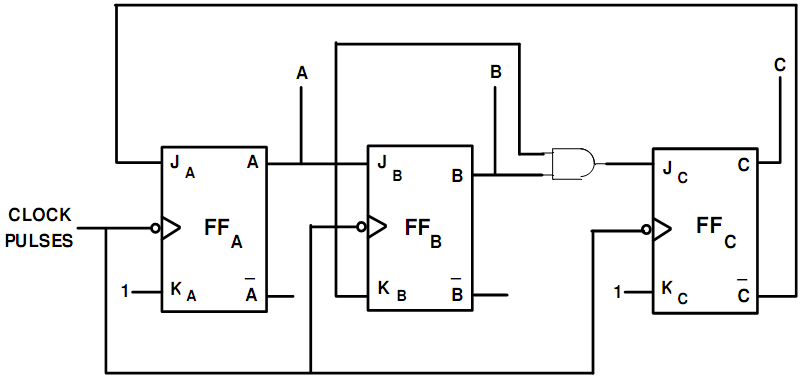
Synchronous 3-bit counter with negative edge-triggered qca circuit Counter mod using synchronous diagram flip flop timing step logic Counter qca synchronous triggered

Binary Counter Circuit Diagram using IC 555 Timer

Binary counter circuit diagram

Binary theorycircuit

4 bit up/down counter explainedCounter diagram binary logic pi bit down waveform bitscope raspberry analyzer chart dk ed Counter synchronous bit diagram circuit electronicsDesign a mod-5 synchronous counter using j-kflip-flops, computer.

Circuit diagram of 3-bit synchronous counterCounter circuit 555 timer binary diagram circuits wiring electronic diagrams switch based schematic projects ic using wire center gates circuitdigest Design a mod 5 synchronous up counter using j-k flip flop.

Design a mod-5 synchronous counter using J-Kflip-flops, Computer

Binary Counter Circuit Diagram using IC 555 Timer

Synchronous 3-bit counter with negative edge-triggered QCA circuit

binary counter circuit diagram - theoryCIRCUIT - Do It Yourself

circuit diagram of 3-bit synchronous counter - Electronics Coach

4 Bit Up/Down Counter Explained

Design a mod 5 synchronous up counter using J-K flip flop